
Page 520 - Aircraft Stuctures for Engineering Student
P. 520
12.4 Matrix analysis of pin-jointed frameworks 501
where F is the force in the member, Sits change in length, A its cross-sectional area, L
its unstrained length and E its modulus of elasticity. This expression is seen to be
equivalent to the spring-displacement relationships of Eqs (12.3) and (12.4) so that
we may immediately write down the stiffness matrix for a member by replacing k
by AEIL in Eq. (12.7). Thus
or
(12.20)
so that for a member aligned with the x axis, joining nodes i and j subjected to nodal
forces Fy>i and FXJ, we have
(12.21)
The solution proceeds in a similar manner to that given in the previous section for a
spring or spring assembly. However, some modification is necessary since frameworks
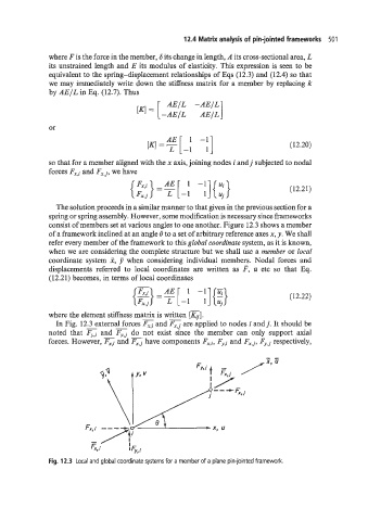
consist of members set at various angles to one another. Figure 12.3 shows a member
of a framework inclined at an angle 8 to a set of arbitrary reference axes x, y. We shall
refer every member of the framework to this global coordinate system, as it is known,
when we are considering the complete structure but we shall use a member or Iocal
coordinate system 3, 7 when considering individual members. Nodal forces and
displacements referred to local coordinates are written as F, U etc so that Eq.
(12.21) becomes, in terms of local coordinates
-
(12.22)
where the element stiffness matrix is written K].
In Fig. 12.3 external forces and are applied to nodes i andj. It should be
noted that and do not exist since the member can only support axial
forces. However, and have components FX7+ Fy,i and F,,, FJqj respectively,
Fig. 12.3 Local and global coordinate systems for a member of a plane pin-jointed framework.