
Page 516 - Aircraft Stuctures for Engineering Student
P. 516
12.3 Stiffness matrix for two elastic springs in line 497
By superposition of these two conditions we obtain relationships between the applied
forces and the nodal displacements for the state when uI = u1 and u2 = u2. Thus
(12.5)
Writing Eqs (12.5) in matrix form we have
(12.6)
and by comparison with Eq. (12.1) we see that the stiffness matrix for this spring
element is
[K] = [ -"]
-k k (12.7)
which is a symmetric matrix of order 2 x 2.
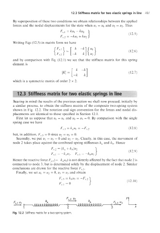
Bearing in mind the results of the previous section we shall now proceed, initially by
a similar process, to obtain the stiffness matrix of the composite two-spring system
shown in Fig. 12.2. The notation and sign convention for the forces and nodal dis-
placements are identical to those specified in Section 12.1.
First let us suppose that u1 = uI and u2 = u3 = 0. By comparison with the single
spring case we have
FY.1 = kaul = -Fr,2 (12.8)
but, in addition, Fr33 = 0 since u2 = u3 = 0.
Secondly, we put ul = u3 = 0 and u2 = u2. Clearly, in this case, the movement of
node 2 takes place against the combined spring stiffnesses k, and kb. Hence
Fy.2 = (ka f kb)U2 1 (12.9)
Fy,I = -k,tt2, Fy13 = -kbU2
Hence the reactive force Fr,l (=-kau2) is not directly affected by the fact that node 2 is
connected to node 3, but is determined solely by the displacement of node 2. Similar
conclusions are drawn for the reactive force Fy:u,3.
Finally, we set uI = u2 = 0, u3 = u3 and obtain
(12. IO)
Fig. 12.2 Stiffness matrix for a two-spring system