Page 517 - Aircraft Stuctures for Engineering Student
P. 517
498  Matrix methods of structural analysis

                    Superimposing these three displacement states we have, for the condition u1 = ul,
                  u2  = 242,  u3  = u3

                                      Fx,1 = kau1  - kau2
                                      Fx,2 = -kul  -k (ka -k kb)u2 - kbu3  1        (12.11)
                                      Fx,3 = -kbU2  -k kbU3

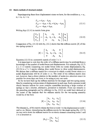
                                    { ::} = [ -: 4.1 { ::}                          (12.12)
                  Writing Eqs (12.11) in matrix form gives
                                                ka
                                                      -ka
                                                     k:-:

                  Comparison of Eq. (12.12) with Eq. (12.1) shows that the stiffness matrix [Kl of this
                  two-spring system is
                                               [ 0  4.1
                                                 ka
                                                       -ka
                                         [q =  -k,   ka+kb                          (12.13)
                                                       -kb

                  Equation (12.13) is a symmetric matrix of order 3 x 3.
                    It is important to note that the order of a stiffness matrix may be predicted from a
                  knowledge of the number of nodal forces and displacements. For example, Eq. (12.7)
                  is a  2 x 2 matrix connecting two  nodal  forces with  two nodal  displacements; Eq.
                  (12.13) is a  3 x 3 matrix relating three nodal forces to  three nodal displacements.
                  We deduce that a stiffness matrix for a structure in which n nodal forces relate to n
                  nodal displacements will  be  of order n x n. The order of the stiffness matrix does
                  not, however, bear a direct relation to the number of nodes in a structure since it is
                  possible for more than one force to be acting at any one node.
                    So far we have built up the stiffness matrices for the single- and two-spring assem-
                  blies by considering various states of displacement in each case. Such a process would
                  clearly become tedious for more complex assemblies involving a  large number of
                  springs so that a shorter, alternative, procedure is desirable. From our remarks in
                  the preceding paragraph and by reference to Eq. (12.2) we  could have deduced at
                  the  outset  of  the  analysis that  the  stiffness matrix  for  the  two-spring assembly
                  would be of the form

                                                   kll  kl2  k13
                                            [lul =  k21  k22                        (12.14)
                                                  [ k31   k32
                  The element kl  of this matrix relates the force at node 1  I the displacemen  at node 1
                  and so on. Hence, remembering the stiffness matrix for the single spring (Eq. (12.7))
                  we may write down the stiffness matrix for an elastic element connecting nodes 1 and
                  2 in a structure as

                                                      kll  kl2                      (12.15)
                                              [K121 = [ k21  k22]

