
Page 530 - Aircraft Stuctures for Engineering Student
P. 530
12.7 Stiffness matrix for a uniform beam 51 1
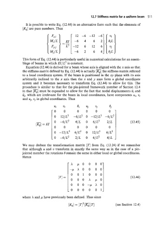
It is possible to write Eq. (12.44) in an alternative form such that the elements of
[KJ are pure numbers. Thus
12 -6 -12 -6
-64 6 2
-12 6 12 6
-62 6 4
This form of Eq. (12.44) is particularly useful in numerical calculations for an assem-
blage of beams in which EI/L3 is constant.
Equation (12.44) is derived for a beam whose axis is aligned with the x axis so that
the stiffness matrix defined by Eq. (12.44) is actually the stiffness matrix referred
to a local coordinate system. If the beam is positioned in the xy plane with its axis
arbitrarily inclined to the x axis then the x and y axes form a global coordinate
system and it becomes necessary to transform Eq. (12.44) to allow for this. The
procedure is similar to that for the pin-jointed framework member of Section 12.4
in that [K,] must be expanded to allow for the fact that nodal displacements iij and
Uj, which are irrelevant for the beam in local coordinates, have components uj, vi
and uj, vj in global coordinates. Thus
ui vi 8i uj vj
0 0 0 0 0 0
o 121~~ -61~~ -121~~ -61~~
o
0 -6/L2 4/L 0 6/L2 2/L (12.45)
= EI
0 0 0 0 0 0
o
o -121~~ 61~~ 121~~ 61~~
0 -6/L2 2/L 0 6/L2 4/L ,
We may deduce the transformation matrix [TI from Eq. (12.24) if we remember
that although u and w transform in exactly the same way as in the case of a pin-
jointed member the rotations B remain the same in either local or global coordinates.
Hence
'A /.Lo 0 00
-/.LAO 0 00
0 01 0 00
[TI = (12.46)
0 00 x p o
0 00-/.LAO
-0 00 0 01
where A and p have previously been defined. Thus since
(see Section 12.4)