
Page 531 - Aircraft Stuctures for Engineering Student
P. 531
51 2 Matrix methods of structural analysis
- 12J/~~ SYM
-12~~1~~ 12~~1~~
6p/L2 -6X/L2 4/L
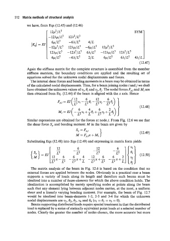
[Kg] = EI
-6p/~2
-12p2/~3 12~~1~~ 12p2/~3
12~~1~~ -12~~1~~ 6x1~~ -12~~1~~ 12~~1~~
- 6p/L2 -6X/L2 2/L 6p/L2 6X/L2 4XIL
(12.47)
Again the stiffness matrix for the complete structure is assembled from the member
stiffness matrices, the boundary conditions are applied and the resulting set of
equations solved for the unknown nodal displacements and forces.
The internal shear forces and bending moments in a beam may be obtained in terms
of the calculated nodal displacements. Thus, for a beam joining nodes i andj we shall
have obtained the unknown values of vi, Bi and vi, 0,. The nodal forces Fy,i and Mi are
then obtained from Eq. (12.44) if the beam is aligned with the x axis. Hence
Similar expressions are obtained for the forces at nodej. From Fig. 12.6 we see that
the shear force S, and bending moment M in the beam are given by
(12.49)
Substituting Eqs (12.48) into Eqs (12.49) and expressing in matrix form yields
12 6 12 6
-- --
L2 L3 (12.50)
6
{2}=E'[12z -x - - 6 6 4 -- 12 x+- 6 -- 2
L3 L2 -zx+z L3 L2 L2X+Z
The matrix analysis of the beam in Fig. 12.6 is based on the condition that no
external forces are applied between the nodes. Obviously in a practical case a beam
supports a variety of loads along its length and therefore such beams must be
idealized into a number of beam-elements for which the above condition holds. The
idealization is accomplished by merely specifying nodes at points along the beam
such that any element lying between adjacent nodes cames, at the most, a uniform
shear and a linearly varying bending moment. For example, the beam of Fig. 12.7
would be idealized into beam-elements 1-2, 2-3 and 3-4 for which the unknown
nodal displacements are v2, S2, 03, v4 and 0, (q = = v3 = 0).
Beams supporting distributed loads require special treatment in that the distributed
load is replaced by a series of statically equivalent point loads at a selected number of
nodes. Clearly the greater the number of nodes chosen, the more accurate but more