
Page 534 - Aircraft Stuctures for Engineering Student
P. 534
12.7 Stiffness matrix for a uniform beam 515
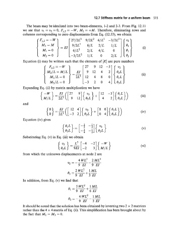
The beam may be idealized into two beam-elements, 1-2 and 2-3. From Fig. 12.11
we see that v1 = v3 = 0, FJ,2 = - W, M2 = +M. Therefore, eliminating rows and
columns corresponding to zero displacements from Eq. (12.53), we obtain
Fy,2 = - W 27/2L3 9/2L2 6/L' -3/2L2
9/2L2 6/L 2/L
6/L2 2/L 4/L 0
-3/2L2 1/L 0 2/L
Equation (i) may be written such that the elements of [Kl are pure numbers
Fy,z = - W 27 9 12 -3 212
4 2 !][ iz}
9 12 4
8
( M3/L = 0 -3 12 0
Expanding Eq. (iij by matrix multiplication we have
and
Equation (iv) gives
Substituting Eq. (v) in Eq. (iii) we obtain
L3 -4 -2
{ cL}=z[-2 3]{ M;}
from which the unknown displacements at node 2 are
4 WL3 2ML'
v2=------
9 EI 9 EI
2WL2 1ML
+--
"=GT 3 EI
In addition, from Eq. (v) we find that
5WL2 1ML
0, = --+--
9 EI 6 EI
4WL2 1ML
o3 = - -- - --
9 EI 3 EI
It should be noted that the solution has been obtained by inverting two 2 x 2 matrices
rather than the 4 x 4 matrix of Eq. (ii). This simplification has been brought about by
the fact that MI = M3 = 0.