Page 535 - Aircraft Stuctures for Engineering Student
P. 535
516  Matrix methods of structural analysis

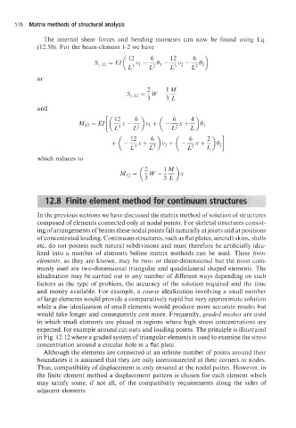
               The  internal  shear  forces  and  bending  moments  can  now  be  found  using  Eq.
             (12.50). For the beam-element  1-2 we have


             or
                                               2     1M
                                         sr,,2 - w - --
                                             =
                                               3     3L
             and
                                                   (
                          M12=EI[(~~-$)~l+ -$x+t)QI


             which reduces to


             _.
               12.8  Finite element method for continuum structures


             In the previous sections we have discussed the matrix method of solution of structures
             composed of elements connected only at nodal points. For skeletal structures consist-
             ing of arrangements of beams these nodal points fall naturally at joints and at positions
             of concentrated loading. Continuum structures, such as flat plates, aircraft skins, shells
             etc, do not possess such natural subdivisions and must therefore be artificially idea-
             lized into a  number  of  elements before matrix  methods can  be  used.  These finite
             elements, as they are known, may be two- or three-dimensional but the most com-
             monly used are two-dimensional  triangular and quadrilateral shaped elements. The
             idealization may be carried out in any number of different ways depending on such
             factors as the type of problem, the accuracy of the solution  required  and the time
             and money available. For example, a coarse idealization  involving a small number
             of large elements would provide a comparatively rapid but very approximate solution
             while a jine idealization  of small elements would produce more accurate results but
             would take longer and consequently cost more. Frequently, graded meshes are used
             in which small elements are placed in regions where high stress concentrations  are
             expected, for example around cut-outs and loading points. The principle is illustrated
             in Fig. 12.12 where a graded system of triangular elements is used to examine the stress
             concentration around a circular hole in a flat plate.
               Although the elements are connected at an infinite number of points around their
             boundaries it is assumed that they are only interconnected at their corners or nodes.
             Thus, compatibility of displacement is only ensured at the nodal points. However, in
             the finite element method a displacement  pattern is chosen for each element which
             may  satisfy  some,  if  not  all,  of  the  compatibility  requirements  along  the  sides of
             adjacent elements.

