Page 540 - Aircraft Stuctures for Engineering Student
P. 540

12.8 Finite element method for continuum structures  521

              Hence
                          -  --  +-
                              6
                                  12x-
                             L2   L3
                              4  6x
                            --+-
                     = J  L   L  L2   [EI] --+-   12x  4  6x  6
                                              6
                                                      --+-
                        0    6   12x      [  L'   L3   L  L2
                            L2   L3
                              2  6x
                            --+-
                          -   L  L2-
                                                              6L 1
              which gives
                                             12   -6L   -12   -6L
                                       EI  -6L    4L2   6L   2L2
                                 [R1=z[  12                                     (12.77)
                                            -12
                                                  6L
                                            -6L   2L2  6L    4L2
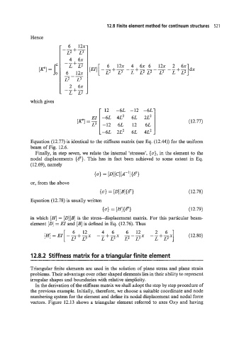
              Equation (12.77) is identical to the stiffness matrix (see Eq. (12.44)) for the uniform
              beam of Fig. 12.6.
                Finally, in step seven, we relate the internal 'stresses',  {cr},  in the element to the
              nodal  displacements {@}. This has  in  fact  been  achieved to  some extent  in  Eq.
              (1 2.69), namely

                                        (0) = [~1[C1[A-'I{Se)
              or, from the above
                                           (01 = [Dl[B1{Se)                     (12.78)
              Equation (12.78) is usually written
                                            (4 [II{@l                           (12.79)
                                               =
              in which  [HI = [D][B] is the stress-displacement  matrix. For this particular beam-
              element [D] = EI  and [B] is defined in Eq. (12.76). Thus
                                                      612
                                                6
                                           4
                               6
                                    12
                    'H] =    - - + -x    - - + --x   - - -               ]      (12.80)
                                                     L2  L3x  --+--x
                            [  L2   L3     L  L'                  L  L2
              12.8.2  Stiffness matrix for a triangular finite element
              Triangular finite elements are used in the solution of plane stress and plane strain
              problems. Their advantage over other shaped elements lies in their ability to represent
              irregular shapes and boundaries with relative simplicity.
                In the derivation of the stiffness matrix we shall adopt the step by step procedure of
              the previous example. Initially, therefore, we choose a suitable coordinate and node
              numbering system for the element and define its nodal displacement and nodal force
              vectors. Figure  12.13 shows a triangular element referred to axes Oxy and having
   535   536   537   538   539   540   541   542   543   544   545