
Page 541 - Aircraft Stuctures for Engineering Student
P. 541
522 Matrix methods of structural analysis
I -X
0
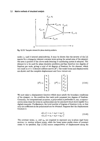
Fig. 12.13 Triangular element for plane elasticity problems.
nodes i, j and k lettered anticlockwise. It may be shown that the inverse of the [A]
matrix for a triangular element contains terms giving the actual area of the element;
this area is positive if the above node lettering or numbering system is adopted. The
element is to be used for plane elasticity problems and has therefore two degrees of
freedom per node, giving a total of six degrees of freedom for the element, which
will result in a 6 x 6 element stiffness matrix [PI. The nodal forces and displacements
are shown and the complete displacement and force vectors are
(12.81)
We now select a displacement function which must satisfy the boundary conditions
of the element, i.e. the condition that each node possesses two degrees of freedom.
Generally, for computational purposes, a polynomial is preferable to, say, a trigono-
metric series since the terms in a polynomial can be calculated much more rapidly by a
digital computer. Furthermore, the total number of degrees of freedom is six, so that
only six coefficients in the polynomial can be obtained. Suppose that the displacement
function is
(12.82)
The constant terms, al and a4, are required to represent any in-plane rigid body
motion, i.e. motion without strain, while the linear terms enable states of constant
strain to be specified; Eqs (12.82) ensure compatibility of displacement along the