
Page 536 - Aircraft Stuctures for Engineering Student
P. 536
12.8 Finite element method for continuum structures 51 7
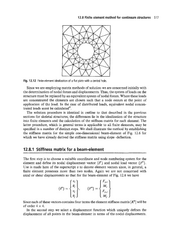
Fig. 12.12 Finite element idealization of a flat plate with a central hole.
Since we are employing matrix methods of solution we are concerned initially with
the determination of nodal forces and displacements. Thus, the system of loads on the
structure must be replaced by an equivalent system of nodal forces. Where these loads
are concentrated the elements are chosen such that a node occurs at the point of
application of the load. In the case of distributed loads, equivalent nodal concen-
trated loads must be calculated4.
The solution procedure is identical in outline to that described in the previous
sections for skeletal structures; the differences lie in the idealization of the structure
into finite elements and the calculation of the stiffness matrix for each element. The
latter procedure, which in general terms is applicable to all finite elements, may be
specified in a number of distinct steps. We shall illustrate the method by establishing
the stiffness matrix for the simple one-dimensional beam-element of Fig. 12.6 for
which we have already derived the stiffness matrix using slope-deflection.
12.8.1 Stiff ness matrix for a beam-element
The first step is to choose a suitable coordinate and node numbering system for the
element and define its nodal displacement vector {CY} and nodal load vector {Fe}.
Use is made here of the superscript e to denote element vectors since, in general, a
finite element possesses more than two nodes. Again we are not concerned with
axial or shear displacements so that for the beam-element of Fig. 12.6 we have
Since each of these vectors contains four terms the element stiffness matrix [K"] will be
of order 4 x 4.
In the second step we select a displacement function which uniquely defines the
displacement of all points in the beam-element in terms of the nodal displacements.