
Page 542 - Aircraft Stuctures for Engineering Student
P. 542
12.8 Finite element method for continuum structures 523
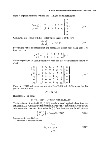
edges of adjacent elements. Writing Eqs (12.82) in matrix form gives
{%;} = [o 0 0 1 x y (12.83)
Comparing Eq. (12.83) with Eq. (12.55) we see that it is of the form
(12.84)
Substituting values of displacement and coordinates at each node in Eq. (12.84) we
have, for node i
1xiy,o 0 0
] {a>
{;}=[ 0 0 0 1x;y,
Similar expressions are obtained for nodes j and k so that for the complete element we
obtain
(12.85)
b
From Eq. (12.81) and by comparison with Eqs (12.58) d (12.59) we see that Eq.
(12.85) takes the form
{fl} = [AI{d
Hence (step 3) we obtain
{a} = [A-l]{fl} (compare with Eq. (12.60))
The inversion of [A], defined in Eq. (12.85), may be achieved algebraically as illustrated
in Example 12.3. Alternatively, the inversion may be carried out numerically for a parti-
cdar element by computer. Substituting for {a} from the above into Eq. (12.84) gives
(12.86)
(compare with Eq. (12.61)).
The strains in the element are
(12.87)