
Page 94 - Aircraft Stuctures for Engineering Student
P. 94
4.6 Application to deflection problems 79
vertical reaction at B is therefore zero, since both of their corresponding displace-
ments are zero. If we examine Eq. (4.17) we note that Xi is the extension of the ith
member of the framework due to the applied loads PI, P2,. . . P,. Therefore, the
loads Fj in the substitution for Xi in Eq. (4.17) are those corresponding to the loads
PI; P2,. . . , P,,. The term dFi/aP2 in Eq. (4.17) represents the rate of change of Fi
with P2 and is calculated by applying the load P2 to the unloaded frame and determin-
ing the corresponding member loads in terms of Pz. This procedure indicates a
method for obtaining the displacement of either a point on the frame in a direction
not coincident with the line of action of a load or, in fact, a point such as C which
carries no load at all. We place at the point and in the required direction aJictitious
or dummy load, say Pf, the original loads being removed. The loads in the members
due to Pf are then calculated and aF/dPf obtained for each member. Substitution in
Eq. (4.17) produces the required deflection.
It must be pointed out that it is not absolutely necessary to remove the actual loads
during the application of Pf. The force in each member would then be calculated in
terms of the actual loading and Pf. Fi follows by substituting Pf = 0 and dFi/aPf is
found by differentiation with respect to Pf. Obviously the two approaches yield the
same expressions for Fi and aFi/dPf, although the latter is arithmetically clumsier.
Example 4.2
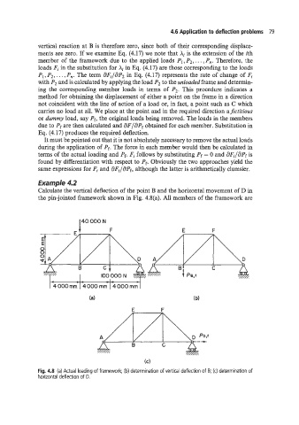
Calculate the vertical deflection of the point B and the horizontal movement of D in
the pin-jointed framework shown in Fig. 4.8(a). All members of the framework are
(C)
Fig. 4.8 (a) Actual loading of framework; (b) determination of vertical deflection of B; (c) determination of
horizontal deflection of D.