
Page 97 - Aircraft Stuctures for Engineering Student
P. 97
4.6 Application to deflection problems 81
linearly elastic and have cross-sectional areas of 1800~'. E for the material of the
members is 200 000 N/mm2.
The members of the framework are linearly elastic so that Eq. (4.17) may be written
or, since each member has the same cross-sectional area and modulus of elasticity
A -XF.L.- 8Fi (ii)
1
AE. lap
r=l
The solution is completed in Table 4.1, in which F are the member forces due to the
actual loading of Fig. 4.8(a), FB,f are the member forces due to the fictitious load PB,f
in Fig. 4.8(b) and FD,f are the forces in the members produced by the fictitious load
PD,p in Fig. 4.8(c). We take tensile forces as positive and compressive forces as
negative.
The vertical deflection of B is
1268 x lo6
AB:v = 1800 x 200 000 = 3.52mm
and the horizontal movement of D is
880 x lo6
= 1800 x 200 000 = 2.44~
The positive values of AB," and AD.h indicate that the deflections are in the directions
of PB,f and PD,p
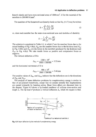
The analysis of beam deflection problems by complementary energy is similar to
that of pin-jointed frameworks, except that we assume initially that displacements
are caused primarily by bending action. Shear force effects are discussed later in
the chapter. Figure 4.9 shows a tip loaded cantilever of uniform cross-section and
length L. The tip load P produces a vertical deflection A, which we require to find.
'Centre of curvature at section z
Fig. 4.9 Beam deflection by the method of complementary energy.