
Page 107 - Amphibionics : Build Your Own Biologically Inspired Robot
P. 107
Amphibionics 04 3/24/03 8:23 AM Page 86
Amphibionics
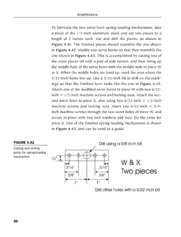
To fabricate the two servo horn spring-loading mechanisms, take
a piece of the 1/2-inch aluminum stock and cut two pieces to a
length of 2 inches each. Cut and drill the pieces, as shown in
Figure 4.41. The finished pieces should resemble the one shown
in Figure 4.42. Modify two servo horns so that they resemble the
one shown in Figure 4.42. This is accomplished by cutting two of
the cross pieces off with a pair of side cutters, and then lining up
the middle hole of the servo horn with the middle hole in piece W
or X. When the middle holes are lined up, mark the area where the
5/32-inch holes line up. Use a 5/32-inch bit to drill on the mark-
ings so that the finished horn looks like the one in Figure 4.42.
Attach one of the modified servo horns to piece W with two 6/32-
inch 1/2-inch machine screws and locking nuts. Attach the sec-
ond servo horn to piece X, also using two 6/32-inch 1/2-inch
machine screws and locking nuts. Insert two 6/32-inch 3/4-
inch machine screws through the two outer holes of piece W, and
secure in place with two lock washers and nuts. Do the same for
piece X. One of the finished spring-loading mechanisms is shown
in Figure 4.43, and can be used as a guide.
FIGURE 4.41
Cutting and drilling
guide for spring-loading
mechanism.
86