
Page 113 - Amphibionics : Build Your Own Biologically Inspired Robot
P. 113
Amphibionics 04 3/24/03 8:24 AM Page 92
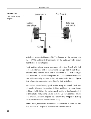
FIGURE 4.50
Limit switch wiring
diagram. Amphibionics
switch, as shown in Figure 4.50. The header will be plugged into
the 5 VDC and the GND connector on the main controller circuit
board later in the chapter.
Next, cut two single-strand connector wires to a length of 5-1/2
inches. Solder one end of each wire to a single-post female head-
er connector, and the other end of each wire to the left and right
limit switches, as shown in Figure 4.50. The limit switch connec-
tors will eventually be attached to microcontroller inputs. Figure
4.51 shows the connectors wired to the limit switches.
Fabricate a 6-volt battery pack holder using 1/16-inch thick alu-
minum by following the cutting, drilling, and bending guide shown
in Figure 4.52. When the battery pack holder is finished, attach it
to the robot’s body using a 6/32-inch 1/2-inch machine screw,
lock washer, and nut. Figure 4.53 shows the completed battery
pack holder fastened to the robot’s body.
At this point, the robot’s mechanical construction is complete. The
next section of Chapter 4 will focus on the electronics.
92