
Page 118 - Amphibionics : Build Your Own Biologically Inspired Robot
P. 118
Amphibionics 04 3/24/03 8:24 AM Page 97
Chapter 4 / Frogbotic: Build Your Own Robotic Frog
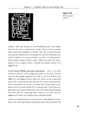
Figure 4.55
PCB foil pattern
artwork.
author’s Web site, located at www.thinkbotics.com, and simply
print the file onto a transparency using a laser or ink-jet printer
with a minimum resolution of 600 dpi. After the artwork has been
successfully transferred to a transparency, use the techniques out-
lined in Chapter 2 to create a board. A 4-inch 6-inch presensi-
tized positive copper board is ideal. When you place the trans-
parency on the copper board, it should be oriented exactly as in
Figure 4.55.
Circuit board drilling and parts placement. Use a 1/32-inch
drill bit to drill all of the component holes on the PCB. Drill the
holes for the voltage regulator (U1) with a 3/64-inch drill bit. Use
Table 4.3 and Figure 4.56 to place the parts on the component
side of the circuit board. Note that the PIC 16F84 microcontroller
(U2) is mounted in an 18-pin I.C. socket. The 18-pin socket is sol-
dered to the PC board and the PIC is inserted after it has been pro-
grammed. Use a fine-toothed saw to cut the board along the guide
lines and drill the mounting holes using a 6/32-inch drill bit.
Figure 4.57 shows the finished main controller board.
Check the finished board for any missed or cold soldered connec-
tions, and verify that all the components have been included. The
97