
Page 115 - Amphibionics : Build Your Own Biologically Inspired Robot
P. 115
Amphibionics 04 3/24/03 8:24 AM Page 94
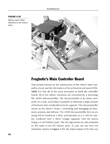
FIGURE 4.53
Battery pack holder
fastened to the robot’s Amphibionics
body.
Frogbotic’s Main Controller Board
This section focuses on the construction of the robot’s main con-
troller circuit and the fabrication of the printed circuit board (PCB).
Table 4.3 lists all of the parts necessary to build the controller
board. All of the robot’s functions are controlled by a Microchip
PIC 16F84 microcontroller. The microcontroller is an entire com-
puter on a chip, and makes it possible to eliminate a large amount
of hardware that would otherwise be required. The microcontroller
serves as the robot’s “brain,” controlling and managing all func-
tions, sensors, and reflexes. The 16F84 microcontroller that we are
using will be clocked at 4 MHz, and operates on a 5-volt DC sup-
ply, produced from a 78L05 voltage regulator, with the source
being a 6-volt battery pack. The two leg servos are also powered
by the same 6-volt DC battery pack. As you can see from the
schematic shown in Figure 4.54, the input/output (I/O) lines are
94