
Page 247 - Amphibionics : Build Your Own Biologically Inspired Robot
P. 247
Amphibionics 06 3/24/03 9:02 AM Page 226
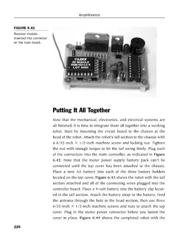
FIGURE 6.41
Receiver module
inserted into connector Amphibionics
on the main board.
Putting It All Together
Now that the mechanical, electronics, and electrical systems are
all finished, it is time to integrate them all together into a working
robot. Start by mounting the circuit board to the chassis at the
head of the robot. Attach the robot’s tail section to the chassis with
a 6/32-inch 1/2-inch machine screw and locking nut. Tighten
the nut with enough torque to let the tail swing freely. Plug each
of the connectors into the main controller, as indicated in Figure
6.42. Note that the motor power supply battery pack can’t be
connected until the top cover has been attached to the chassis.
Place a new AA battery into each of the three battery holders
located on the top cover. Figure 6.43 shows the robot with the tail
section attached and all of the connecting wires plugged into the
controller board. Place a 9-volt battery into the battery clip locat-
ed in the tail section. Attach the battery strap to the battery. Feed
the antenna through the hole in the head section, then use three
6/32-inch 1/2-inch machine screws and nuts to attach the top
cover. Plug in the motor power connector before you fasten the
cover in place. Figure 6.44 shows the completed robot with the
226