
Page 244 - Amphibionics : Build Your Own Biologically Inspired Robot
P. 244
Amphibionics 06 3/24/03 9:02 AM Page 223
Chapter 6 / Crocobot: Build Your Own Robotic Crocodile
Use a 1/32-inch
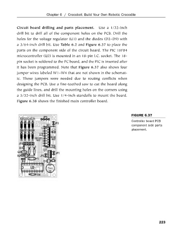
Circuit board drilling and parts placement.
drill bit to drill all of the component holes on the PCB. Drill the
holes for the voltage regulator (U1) and the diodes (D2–D9) with
a 3/64-inch drill bit. Use Table 6.2 and Figure 6.37 to place the
parts on the component side of the circuit board. The PIC 16F84
microcontroller (U2) is mounted in an 18-pin I.C. socket. The 18-
pin socket is soldered to the PC board, and the PIC is inserted after
it has been programmed. Note that Figure 6.37 also shows four
jumper wires labeled W1–W4 that are not shown in the schemat-
ic. These jumpers were needed due to routing conflicts when
designing the PCB. Use a fine-toothed saw to cut the board along
the guide lines, and drill the mounting holes on the corners using
a 5/32-inch drill bit. Use 1/4-inch standoffs to mount the board.
Figure 6.38 shows the finished main controller board.
FIGURE 6.37
Controller board PCB
component side parts
placement.
223