
Page 242 - Amphibionics : Build Your Own Biologically Inspired Robot
P. 242
Amphibionics 06 3/24/03 9:02 AM Page 221
Chapter 6 / Crocobot: Build Your Own Robotic Crocodile
these devices very easy by mounting the modules on small circuit
boards with connectors and a place to solder on the antennas
(which are included with the modules).
The LC Series is ideally suited for volume use in applications such
as remote control, security, identification, robotics, and periodic
data transfer. Packaged in a compact SMD package, the LC trans-
mitter utilizes a highly optimized SAW architecture to achieve an
unmatched blend of performance, size, efficiency, and cost. When
paired with a matching LC series receiver, a highly reliable wire-
less link is formed, capable of transferring serial data at distances
in excess of 300 feet. No external RF components, except an
antenna, are required, making design integration straightforward.
The features include: low cost, no external RF components
required, ultra-low power consumption, compact surface-mount
package, stable SAW–based architecture, support data rates to
5,000 bps, wide supply range (2.7-5.2 vdc), direct serial interface,
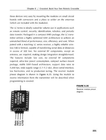
low harmonics, and no production tuning. The receiver module
pinout diagram is shown in Figure 6.35. Using the module to
receive information from the transmitter will be described when
programming is covered.
FIGURE 6.35
Receiver module pinout
diagram.
221