
Page 237 - Amphibionics : Build Your Own Biologically Inspired Robot
P. 237
Amphibionics 06 3/24/03 9:02 AM Page 216
Amphibionics
The Controller Circuit Board
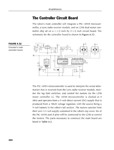
The robot’s main controller will integrate a PIC 16F84 microcon-
troller, a Lynx radio receiver module, and an L298 dual motor con-
troller chip all on a 1-1/2 inch by 2-1/2 inch circuit board. The
schematic for the controller board is shown in Figure 6.32.
FIGURE 6.32
Crocobot’s main
controller board.
The PIC 16F84 microcontroller is used to interpret the serial infor-
mation that is received from the Lynx radio receiver module, mon-
itor the leg limit switches, and control the motors via the L298
motor controller I.C. The 16F84 microcontroller is clocked at 4
MHz and operates from a 5-volt direct current (DC) supply that is
produced from a 78L05 voltage regulator, with the source being a
9-volt battery in the robot’s tail section. The motors operate from
their own 4.5-volt supply contained in the robot’s top cover. Six of
the PIC 16F84 port B pins will be connected to the L298 to control
the motors. The parts necessary to construct the main board are
listed in Table 6.2.
216