
Page 239 - Amphibionics : Build Your Own Biologically Inspired Robot
P. 239
Amphibionics 06 3/24/03 9:02 AM Page 218
Amphibionics
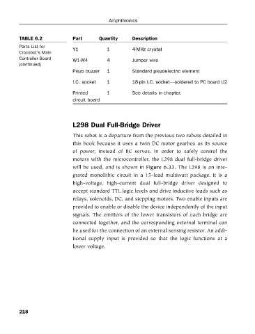
TABLE 6.2
Parts List for
4-MHz crystal
1
Y1
Crocobot’s Main Part Quantity Description
Controller Board W1-W4 4 Jumper wire
(continued)
Piezo buzzer 1 Standard piezoelectric element
I.C. socket 1 18-pin I.C. socket—soldered to PC board U2
Printed 1 See details in chapter.
circuit board
L298 Dual Full-Bridge Driver
This robot is a departure from the previous two robots detailed in
this book because it uses a twin DC motor gearbox as its source
of power, instead of RC servos. In order to safely control the
motors with the microcontroller, the L298 dual full-bridge driver
will be used, and is shown in Figure 6.33. The L298 is an inte-
grated monolithic circuit in a 15-lead multiwatt package. It is a
high-voltage, high-current dual full-bridge driver designed to
accept standard TTL logic levels and drive inductive loads such as
relays, solenoids, DC, and stepping motors. Two enable inputs are
provided to enable or disable the device independently of the input
signals. The emitters of the lower transistors of each bridge are
connected together, and the corresponding external terminal can
be used for the connection of an external sensing resistor. An addi-
tional supply input is provided so that the logic functions at a
lower voltage.
218