
Page 245 - Amphibionics : Build Your Own Biologically Inspired Robot
P. 245
Amphibionics 06 3/24/03 9:02 AM Page 224
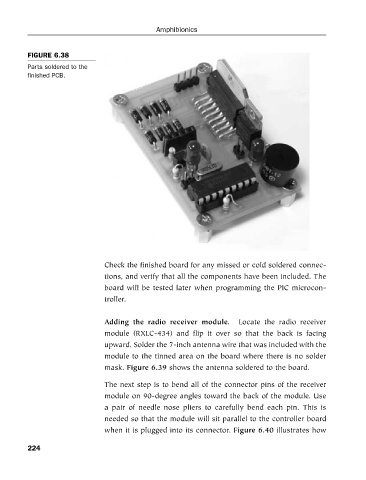
FIGURE 6.38
Parts soldered to the
finished PCB. Amphibionics
Check the finished board for any missed or cold soldered connec-
tions, and verify that all the components have been included. The
board will be tested later when programming the PIC microcon-
troller.
Adding the radio receiver module. Locate the radio receiver
module (RXLC-434) and flip it over so that the back is facing
upward. Solder the 7-inch antenna wire that was included with the
module to the tinned area on the board where there is no solder
mask. Figure 6.39 shows the antenna soldered to the board.
The next step is to bend all of the connector pins of the receiver
module on 90-degree angles toward the back of the module. Use
a pair of needle nose pliers to carefully bend each pin. This is
needed so that the module will sit parallel to the controller board
when it is plugged into its connector. Figure 6.40 illustrates how
224