
Page 255 - Amphibionics : Build Your Own Biologically Inspired Robot
P. 255
Amphibionics 06 3/24/03 9:02 AM Page 234
Amphibionics
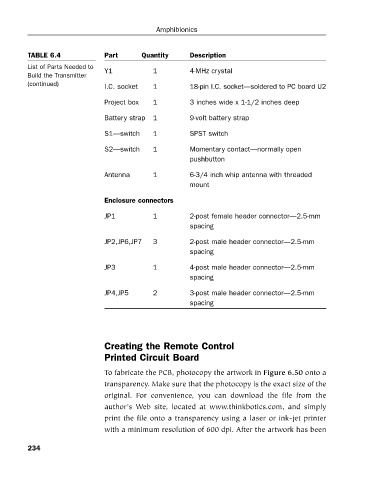
TABLE 6.4
List of Parts Needed to
Y1
4-MHz crystal
1
Build the Transmitter Part Quantity Description
(continued) I.C. socket 1 18-pin I.C. socket—soldered to PC board U2
Project box 1 3 inches wide x 1-1/2 inches deep
Battery strap 1 9-volt battery strap
S1—switch 1 SPST switch
S2—switch 1 Momentary contact—normally open
pushbutton
Antenna 1 6-3/4 inch whip antenna with threaded
mount
Enclosure connectors
JP1 1 2-post female header connector—2.5-mm
spacing
JP2,JP6,JP7 3 2-post male header connector—2.5-mm
spacing
JP3 1 4-post male header connector—2.5-mm
spacing
JP4,JP5 2 3-post male header connector—2.5-mm
spacing
Creating the Remote Control
Printed Circuit Board
To fabricate the PCB, photocopy the artwork in Figure 6.50 onto a
transparency. Make sure that the photocopy is the exact size of the
original. For convenience, you can download the file from the
author’s Web site, located at www.thinkbotics.com, and simply
print the file onto a transparency using a laser or ink-jet printer
with a minimum resolution of 600 dpi. After the artwork has been
234