
Page 257 - Amphibionics : Build Your Own Biologically Inspired Robot
P. 257
Amphibionics 06 3/24/03 9:02 AM Page 236
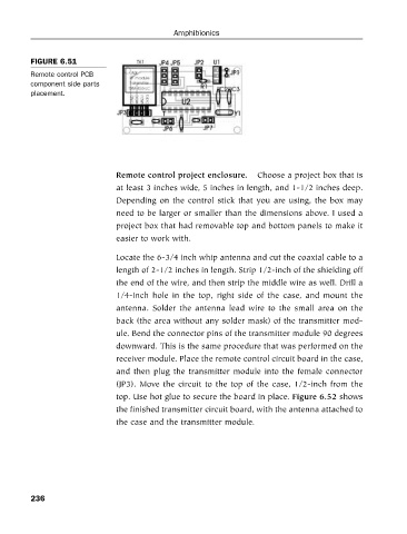
FIGURE 6.51
Remote control PCB
component side parts Amphibionics
placement.
Remote control project enclosure. Choose a project box that is
at least 3 inches wide, 5 inches in length, and 1-1/2 inches deep.
Depending on the control stick that you are using, the box may
need to be larger or smaller than the dimensions above. I used a
project box that had removable top and bottom panels to make it
easier to work with.
Locate the 6-3/4 inch whip antenna and cut the coaxial cable to a
length of 2-1/2 inches in length. Strip 1/2-inch of the shielding off
the end of the wire, and then strip the middle wire as well. Drill a
1/4-inch hole in the top, right side of the case, and mount the
antenna. Solder the antenna lead wire to the small area on the
back (the area without any solder mask) of the transmitter mod-
ule. Bend the connector pins of the transmitter module 90 degrees
downward. This is the same procedure that was performed on the
receiver module. Place the remote control circuit board in the case,
and then plug the transmitter module into the female connector
(JP3). Move the circuit to the top of the case, 1/2-inch from the
top. Use hot glue to secure the board in place. Figure 6.52 shows
the finished transmitter circuit board, with the antenna attached to
the case and the transmitter module.
236