
Page 256 - Amphibionics : Build Your Own Biologically Inspired Robot
P. 256
Amphibionics 06 3/24/03 9:02 AM Page 235
Chapter 6 / Crocobot: Build Your Own Robotic Crocodile
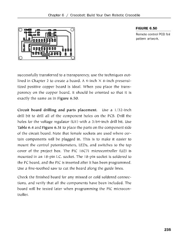
FIGURE 6.50
Remote control PCB foil
pattern artwork.
successfully transferred to a transparency, use the techniques out-
lined in Chapter 2 to create a board. A 4-inch 6-inch presensi-
tized positive copper board is ideal. When you place the trans-
parency on the copper board, it should be oriented so that it is
exactly the same as in Figure 6.50.
Circuit board drilling and parts placement. Use a 1/32-inch
drill bit to drill all of the component holes on the PCB. Drill the
holes for the voltage regulator (U1) with a 3/64-inch drill bit. Use
Table 6.4 and Figure 6.51 to place the parts on the component side
of the circuit board. Note that female sockets are used where cer-
tain components will be plugged in. This is to make it easier to
mount the control potentiometers, LEDs, and switches to the top
cover of the project box. The PIC 16C71 microcontroller (U2) is
mounted in an 18-pin I.C. socket. The 18-pin socket is soldered to
the PC board, and the PIC is inserted after it has been programmed.
Use a fine-toothed saw to cut the board along the guide lines.
Check the finished board for any missed or cold soldered connec-
tions, and verify that all the components have been included. The
board will be tested later when programming the PIC microcon-
troller.
235