
Page 320 - Amphibionics : Build Your Own Biologically Inspired Robot
P. 320
Amphibionics 07 3/24/03 9:13 AM Page 299
Chapter 7 / Turtletron: Build Your Own Robotic Turtle
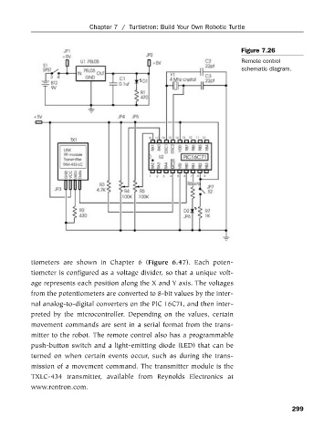
Figure 7.26
Remote control
schematic diagram.
tiometers are shown in Chapter 6 (Figure 6.47). Each poten-
tiometer is configured as a voltage divider, so that a unique volt-
age represents each position along the X and Y axis. The voltages
from the potentiometers are converted to 8-bit values by the inter-
nal analog-to-digital converters on the PIC 16C71, and then inter-
preted by the microcontroller. Depending on the values, certain
movement commands are sent in a serial format from the trans-
mitter to the robot. The remote control also has a programmable
push-button switch and a light-emitting diode (LED) that can be
turned on when certain events occur, such as during the trans-
mission of a movement command. The transmitter module is the
TXLC-434 transmitter, available from Reynolds Electronics at
www.rentron.com.
299