
Page 76 - Amphibionics : Build Your Own Biologically Inspired Robot
P. 76
Amphibionics 04 3/24/03 8:23 AM Page 55
Chapter 4 / Frogbotic: Build Your Own Robotic Frog
cuit constantly compares the potentiometer signal to the input
control signal provided by the microcontroller. The internal com-
parator moves the motor shaft and potentiometer either forward
or in reverse, until the two signals are the same. Because of the
feedback control circuit, the rotor can be accurately positioned
and will maintain the position as long as the input control signal
is applied. The shaft of the motor can be positioned through 180
degrees of rotation, depending on the width of the input signal.
The PicBasic Pro language makes servo control with a PIC micro-
controller easy, using a command called Pulsout. The syntax is
Pulsout Pin, Period. A pulse is generated on Pin of specified
Period. Toggling the pin twice generates the pulse; thus, the initial
state of the pin determines the polarity of the pulse. Pin is auto-
matically made an output. Pin may be a constant, 0–15, or a vari-
able that contains a number between 0 and 15 (e.g., B0) or a pin
name (e.g., PORTA.0).
The resolution of Pulsout is dependent on the oscillator frequen-
cy. Since we are using a 4-MHz oscillator, the Period of the gener-
ated pulse will be in 10 microsecond increments. To send a pulse
to port B on pin 7 that is 1.4 ms long (at 4 MHz, 10 µs 140
1400 µs or 1.4 ms), the command would be: Pulsout PortB.7,140.
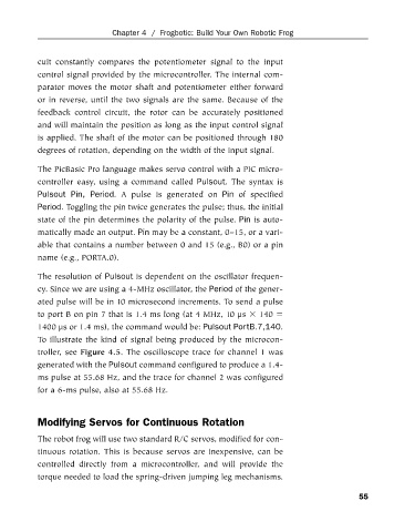
To illustrate the kind of signal being produced by the microcon-
troller, see Figure 4.5. The oscilloscope trace for channel 1 was
generated with the Pulsout command configured to produce a 1.4-
ms pulse at 55.68 Hz, and the trace for channel 2 was configured
for a 6-ms pulse, also at 55.68 Hz.
Modifying Servos for Continuous Rotation
The robot frog will use two standard R/C servos, modified for con-
tinuous rotation. This is because servos are inexpensive, can be
controlled directly from a microcontroller, and will provide the
torque needed to load the spring-driven jumping leg mechanisms.
55