
Page 161 - An Introduction to Microelectromechanical Systems Engineering
P. 161
140 MEM Structures and Systems in Photonic Applications
approximately one quarter the wavelength of light in the visible spectrum. In their
resting state, the ribbons appear as a continuous surface to incident light, and normal
reflection occurs. But when an electrostatic voltage pulls down alternate rows of rib-
bons, the light reflecting from the deflected ribbons travels an additional one half of a
wavelength (twice the gap) and thus becomes 180º out of phase with respect to the
light from the stationary ribbons. This effectively turns the ribbons into a phase grat-
ing, diffracting the incident light into higher orders. The angle of diffraction depends
on the wavelength and the pitch—or periodicity—of the ribbons.
The entire display element consists of a two-dimensional array of square pixels,
each approximately 20 µm on a side containing two fixed and two flexible ribbons.
The mechanical structure of the ribbon relies on a thin silicon nitride film under ten-
sion to provide the restoring force in the absence of actuation. The reflecting surface
is a 50-nm-thick aluminum layer. The underlying electrode is made of tungsten iso-
lated from the substrate by silicon dioxide.
The optical projection system includes an aperture mounted over the display ele-
ment (see Figure 5.6). Light-absorbing material surrounding the aperture blocks the
reflected light but allows the first diffraction orders to be imaged by the projection
lens. The incident illumination may be normal to the chip, sending the diffracted
orders off axis. Alternatively, the use of off-axis illumination simplifies the imaging
optics in a scheme similar to projection with the DMD described in the previous
chapter.
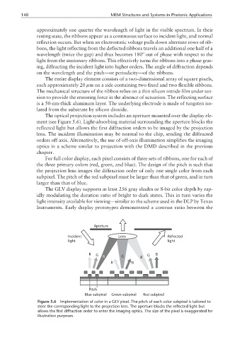
For full color display, each pixel consists of three sets of ribbons, one for each of
the three primary colors (red, green, and blue). The design of the pitch is such that
the projection lens images the diffraction order of only one single color from each
subpixel. The pitch of the red subpixel must be larger than that of green, and in turn
larger than that of blue.
The GLV display supports at least 256 gray shades or 8-bit color depth by rap-
idly modulating the duration ratio of bright to dark states. This in turn varies the
light intensity available for viewing—similar to the scheme used in the DLP by Texas
Instruments. Early display prototypes demonstrated a contrast ratio between the
Aperture
Incident Lens Reflected
light light
R G B G R G B
R B
Pitch
Blue subpixel Green subpixel Red subpixel
Figure 5.6 Implementation of color in a GLV pixel. The pitch of each color subpixel is tailored to
steer the corresponding light to the projection lens. The aperture blocks the reflected light but
allows the first diffraction order to enter the imaging optics. The size of the pixel is exaggerated for
illustration purposes.