
Page 159 - An Introduction to Microelectromechanical Systems Engineering
P. 159
138 MEM Structures and Systems in Photonic Applications
Sacrificial Hinge Yoke Hinge post
Metal-3 level spacer 1 CMP
oxide
Silicon substrate with CMOS circuits
1. Pattern spacer 1 layer 4. Etch yoke and strip oxide
Mirror Mirror mask
Oxide hinge mask Hinge metal Spacer 2
2. Deposit hinge metal; deposit 5. Deposit spacer 2 and mirror
and pattern oxide hinge mask
Mirror Mirror post
Yoke metal Oxide mask
Yoke Hinge
3. Deposit yoke and pattern 6. Pattern mirror and
yoke oxide mask etch sacrificial spacers
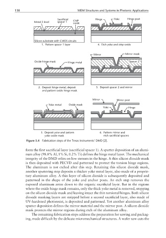
Figure 5.4 Fabrication steps of the Texas Instruments’ DMD [2].
form the first sacrificial layer (sacrificial spacer 1). A sputter deposition of an alumi-
num alloy (98.8% Al, 1% Si, 0.2% Ti) defines the hinge metal layer. The mechanical
integrity of the DMD relies on low stresses in the hinge. A thin silicon dioxide mask
is then deposited with PECVD and patterned to protect the torsion hinge regions.
The aluminum is not etched after this step. Retaining this silicon dioxide mask,
another sputtering step deposits a thicker yoke metal layer, also made of a proprie-
tary aluminum alloy. A thin layer of silicon dioxide is subsequently deposited and
patterned in the shape of the yoke and anchor posts. An etch step removes the
exposed aluminum areas down to the organic sacrificial layer. But in the regions
where the oxide hinge mask remains, only the thick yoke metal is removed, stopping
on the silicon dioxide mask and leaving intact the thin torsional hinges. Both silicon
dioxide masking layers are stripped before a second sacrificial layer, also made of
UV-hardened photoresist, is deposited and patterned. Yet another aluminum alloy
sputter deposition defines the mirror material and the mirror post. A silicon dioxide
mask protects the mirror regions during etch of the aluminum alloy.
The remaining fabrication steps address the preparation for sawing and packag-
ing, made difficult by the delicate micromechanical structures. A wafer saw cuts the