
Page 227 - An Introduction to Microelectromechanical Systems Engineering
P. 227
206 MEM Structures and Systems in RF Applications
reference oscillators, beams are designed for resonant frequencies including 19.2
MHz and 76.8 MHz for code-division multiple access (CDMA) wireless networks
and 26 MHz for Global System for Mobile Communications (GSM) networks.
The bottom electrode and the resonant beam are fabricated from polysilicon
using standard surface micromachining steps, with a sacrificial silicon dioxide layer
in between [23]. A sacrificial oxide layer is also formed on top of the resonant beam,
followed by a sacrificial nickel spacer on the sides of the beam. Gold electroplated
through a photoresist mask forms the top metal electrode. Finally, the nickel and
silicon dioxide are etched away to leave the freestanding beams.
Coupled-Resonator Bandpass Filters
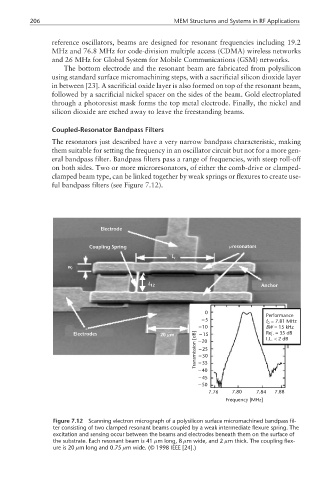
The resonators just described have a very narrow bandpass characteristic, making
them suitable for setting the frequency in an oscillator circuit but not for a more gen-
eral bandpass filter. Bandpass filters pass a range of frequencies, with steep roll-off
on both sides. Two or more microresonators, of either the comb-drive or clamped-
clamped beam type, can be linked together by weak springs or flexures to create use-
ful bandpass filters (see Figure 7.12).
Electrode
Coupling Spring µresonators
L r
w r
L 12 Anchor
0
Performance
−5 = 7.81 MHz
f 0
−10 BW =15kHz
−15
Electrodes 20 m [dB] −20 Rej.=35dB
µ
I.L.<2dB
Transmission −25
−30
−35
−40
−45
−50
7.76 7.80 7.84 7.88
Frequency [MHz]
Figure 7.12 Scanning electron micrograph of a polysilicon surface micromachined bandpass fil-
ter consisting of two clamped resonant beams coupled by a weak intermediate flexure spring. The
excitation and sensing occur between the beams and electrodes beneath them on the surface of
the substrate. Each resonant beam is 41 µm long, 8 µm wide, and 2 µm thick. The coupling flex-
ure is 20 µm long and 0.75 µm wide. (© 1998 IEEE [24].)