
Page 225 - An Introduction to Microelectromechanical Systems Engineering
P. 225
204 MEM Structures and Systems in RF Applications
First-order Motion
resonant frequency: Beam
E t Anchor C oo i o v o
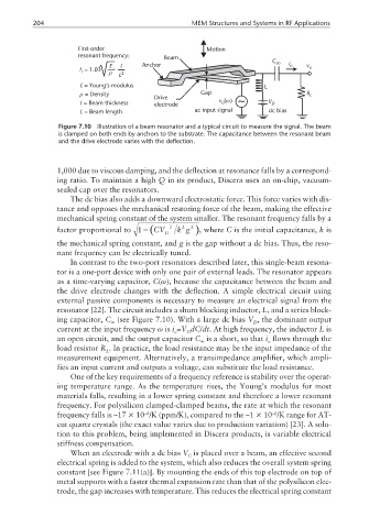
f = 1.03 ρ L 2
r
E = Young’s modulus L
ρ = Density Gap R L
Drive
t = Beam thickness electrode v ()ω V D
a
L = Beam length ac input signal dc bias
Figure 7.10 Illustration of a beam resonator and a typical circuit to measure the signal. The beam
is clamped on both ends by anchors to the substrate. The capacitance between the resonant beam
and the drive electrode varies with the deflection.
1,000 due to viscous damping, and the deflection at resonance falls by a correspond-
ing ratio. To maintain a high Q in its product, Discera uses an on-chip, vacuum-
sealed cap over the resonators.
The dc bias also adds a downward electrostatic force. This force varies with dis-
tance and opposes the mechanical restoring force of the beam, making the effective
mechanical spring constant of the system smaller. The resonant frequency falls by a
2
factor proportional to 1− (CV D 2 k g 2 ), where C is the initial capacitance, k is
the mechanical spring constant, and g is the gap without a dc bias. Thus, the reso-
nant frequency can be electrically tuned.
In contrast to the two-port resonators described later, this single-beam resona-
tor is a one-port device with only one pair of external leads. The resonator appears
as a time-varying capacitor, C(ω), because the capacitance between the beam and
the drive electrode changes with the deflection. A simple electrical circuit using
external passive components is necessary to measure an electrical signal from the
resonator [22]. The circuit includes a shunt blocking inductor, L, and a series block-
ing capacitor, C (see Figure 7.10). With a large dc bias V , the dominant output
D
current at the input frequency ω is i =V dC/dt. At high frequency, the inductor L is
o D
an open circuit, and the output capacitor C is a short, so that i flows through the
o
load resistor R . In practice, the load resistance may be the input impedance of the
L
measurement equipment. Alternatively, a transimpedance amplifier, which ampli-
fies an input current and outputs a voltage, can substitute the load resistance.
One of the key requirements of a frequency reference is stability over the operat-
ing temperature range. As the temperature rises, the Young’s modulus for most
materials falls, resulting in a lower spring constant and therefore a lower resonant
frequency. For polysilicon clamped-clamped beams, the rate at which the resonant
frequency falls is –17 × 10 /K (ppm/K), compared to the –1 × 10 /K range for AT-
–6
–6
cut quartz crystals (the exact value varies due to production variation) [23]. A solu-
tion to this problem, being implemented in Discera products, is variable electrical
stiffness compensation.
When an electrode with a dc bias V is placed over a beam, an effective second
C
electrical spring is added to the system, which also reduces the overall system spring
constant [see Figure 7.11(a)]. By mounting the ends of this top electrode on top of
metal supports with a faster thermal expansion rate than that of the polysilicon elec-
trode, the gap increases with temperature. This reduces the electrical spring constant