
Page 226 - An Introduction to Microelectromechanical Systems Engineering
P. 226
Microelectromechanical Resonators 205
Metal top
compensation
electrode
V D
C
dc bias V dc bias
v ()ω
a
Polysilicon
bottom ac input signal
Polysilicon
resonant drive
beam electrode
(a)
Compensation Anchor
electrode
Raised support
Polysilicon resonant
beam (under metal)
Slit
Polysilicon bottom
drive electrode
(b)
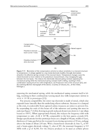
Figure 7.11 Illustration of the compensation scheme to reduce sensitivity in a resonant structure
to temperature. A voltage applied to a top metal electrode modifies through electrostatic
attraction the effective spring constant of the resonant beam. Temperature changes cause the
metal electrode to move relative to the polysilicon resonant beam, thus changing the gap
between the two layers. This reduces the electrically induced spring constant opposing the
mechanical spring while the mechanical spring constant itself is falling, resulting in their
combination varying much less with temperature. (a) Perspective view of the structure [23], and
(b) scanning electron micrograph of the device. (Courtesy of: Discera, Inc., of Ann Arbor,
Michigan.)
opposing the mechanical spring, while the mechanical spring constant itself is fal-
ling, resulting in their combination varying much less with temperature (down to
–6
+0.6 × 10 /K in prototypes [23]).
For process compatibility the entire top electrode is made of metal, which also
expands faster laterally than the underlying silicon substrate. Because it is clamped
at the ends, it undesirably bows upward unless measures are taken to prevent this.
By suspending the ends of this beam off of the substrate and putting slits near its
ends [see Figure 7.11(b)], bowing is greatly reduced, from 6 nm down to 1 nm when
heated to 100ºC. When appropriately biased, this reduces the frequency shift with
temperature to only –0.24 × 10 /K, comparable to the best quartz crystals [23].
–6
Design specifications for this prototype beam are a length of 40 µm, width of 8 µm,
thickness of 2 µm, gap below the resonant beam during operation of 50 nm, and gap
above the beam of about 250 nm. With a beam-lower electrode dc bias V of 8V
D
and a beam-upper electrode voltage V also of 8V, the resonant frequency is 9.9
C
MHz with a Q of 4,100. For the Discera products to be used as cellular phone