
Page 221 - An Introduction to Microelectromechanical Systems Engineering
P. 221
200 MEM Structures and Systems in RF Applications
two free ends meet. An interlocking tongue-in-groove structure aids in alignment
and gives a small amount of process tolerance [Figure 7.5(b)]. The stack coils are
electroplated with 5 to 8 µm of copper for a low resistance, using the gold on both
sides as a seed layer. The copper also fills the etch holes and seals the seam where the
two halves came together. Finally, the photoresist and any remaining release
material are removed.
Microelectromechanical Resonators
A simple mechanical system of a spring with spring constant k and a mass m has a
1
resonant frequency f = () k m at which it naturally oscillates if the mass is
/
r 2π
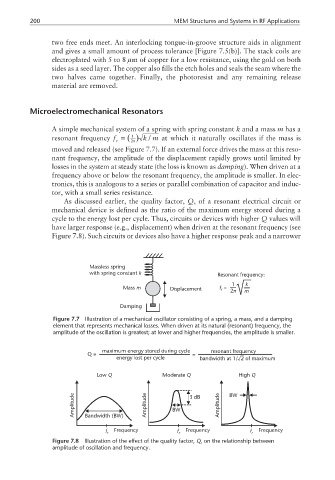
moved and released (see Figure 7.7). If an external force drives the mass at this reso-
nant frequency, the amplitude of the displacement rapidly grows until limited by
losses in the system at steady state (the loss is known as damping). When driven at a
frequency above or below the resonant frequency, the amplitude is smaller. In elec-
tronics, this is analogous to a series or parallel combination of capacitor and induc-
tor, with a small series resistance.
As discussed earlier, the quality factor, Q, of a resonant electrical circuit or
mechanical device is defined as the ratio of the maximum energy stored during a
cycle to the energy lost per cycle. Thus, circuits or devices with higher Q values will
have larger response (e.g., displacement) when driven at the resonant frequency (see
Figure 7.8). Such circuits or devices also have a higher response peak and a narrower
Massless spring
with spring constant k Resonant frequency:
1 k
Mass m Displacement f = 2π m
r
Damping
Figure 7.7 Illustration of a mechanical oscillator consisting of a spring, a mass, and a damping
element that represents mechanical losses. When driven at its natural (resonant) frequency, the
amplitude of the oscillation is greatest; at lower and higher frequencies, the amplitude is smaller.
maximum energy stored during cycle resonant frequency
Q= =
energy lost per cycle bandwidth at 1/ 2 of maximum
Low Q Moderate Q High Q
Amplitude Bandwidth (BW) Amplitude BW 3dB Amplitude BW
f r Frequency f r Frequency f r Frequency
Figure 7.8 Illustration of the effect of the quality factor, Q, on the relationship between
amplitude of oscillation and frequency.