Page 223 - An Introduction to Microelectromechanical Systems Engineering
P. 223

202                                        MEM Structures and Systems in RF Applications

                                                                       Spectrum
                      Electrostatic              Spring beam           analyzer
                      comb actuator
                                                    Electrostatic sense
                                   Shuttle plate                         f r
                                                    comb structure

                       Motion

                                                            v o
                                                        i o      Resonant frequency:
                                                                   1        k total
                                                               f =
                                                                r
                                                     Output        2π  m + 0.25 m + 0.34 m b
                                                                               c
                                                                        p
                                                     resistor
                                Anchors
                             ω
                           v ()                                  k total  = System spring constant
                            a
                           ac input signal                       m = Mass of shuttle
                                                                  p
                                            V D
                                                                  c
                                            Drive dc bias        m = Mass of connector
                                                                 m = Mass of spring beams
                                                                  b
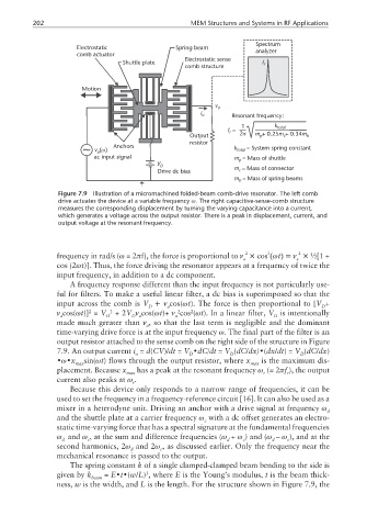
                 Figure 7.9  Illustration of a micromachined folded-beam comb-drive resonator. The left comb
                 drive actuates the device at a variable frequency ω. The right capacitive-sense-comb structure
                 measures the corresponding displacement by turning the varying capacitance into a current,
                 which generates a voltage across the output resistor. There is a peak in displacement, current, and
                 output voltage at the resonant frequency.
                                                                                   2
                                                                          2
                                                                    2
                 frequency in rad/s (ω =2πf), the force is proportional to ν × cos (ωt)=ν × ½[1 +
                                                                    a             a
                 cos (2ωt)]. Thus, the force driving the resonator appears at a frequency of twice the
                 input frequency, in addition to a dc component.
                    A frequency response different than the input frequency is not particularly use-
                 ful for filters. To make a useful linear filter, a dc bias is superimposed so that the
                 input across the comb is V +ν cos(ωt). The force is then proportional to [V +
                                          D    a                                         D
                                                     2
                                                  2
                         2
                 ν cos(ωt)] = V  2  +2V ν cos(ωt)+ ν cos (ωt). In a linear filter, V is intentionally
                  a           D      D a         a                          D
                 made much greater than ν , so that the last term is negligible and the dominant
                                         a
                 time-varying drive force is at the input frequency ω. The final part of the filter is an
                 output resistor attached to the sense comb on the right side of the structure in Figure
                 7.9. An output current i = d(CV)/dt = V •dC/dt = V (dC/dx)•(dx/dt)= V (dC/dx)
                                      o              D          D                  D
                 •ω•x   sin(ωt) flows through the output resistor, where x  is the maximum dis-
                      max                                             max
                 placement. Because x  has a peak at the resonant frequency ω (= 2πf ), the output
                                    max                                  r      r
                 current also peaks at ω .
                                     r
                    Because this device only responds to a narrow range of frequencies, it can be
                 used to set the frequency in a frequency-reference circuit [16]. It can also be used as a
                 mixer in a heterodyne unit. Driving an anchor with a drive signal at frequency ω
                                                                                           d
                 and the shuttle plate at a carrier frequency ω with a dc offset generates an electro-
                                                         c
                 static time-varying force that has a spectral signature at the fundamental frequencies
                 ω and ω , at the sum and difference frequencies (ω + ω ) and (ω – ω ), and at the
                  d      c                                     d    c       d   c
                 second harmonics, 2ω and 2ω , as discussed earlier. Only the frequency near the
                                     d       c
                 mechanical resonance is passed to the output.
                    The spring constant k of a single clamped-clamped beam bending to the side is
                                         3
                 given by k   = E•t•(w/L) , where E is the Young’s modulus, t is the beam thick-
                          beam
                 ness, w is the width, and L is the length. For the structure shown in Figure 7.9, the
   218   219   220   221   222   223   224   225   226   227   228