
Page 276 - An Introduction to Microelectromechanical Systems Engineering
P. 276
Quality Control, Reliability, and Failure Analysis 255
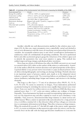
Table 8.9 A Summary of the Environmental Tests Performed in Assessing the Reliability of the DMD
Environmental Test Details Duration
Storage life (cold/hot) −55°C to +100°C, no applied power 1,000 hours
Temperature cycling –55°C to +125°C, air to air, fine/gross leaks 1,000 cycles
Thermal shock –55°C to +125°C, liquid to liquid 200 cycles
Unbiased humidity +85°C/85% RH, no applied power 1,000 cycles
Electrostatic discharge Human body model, 1 positive, 1 negative at 2,000V
Latch up 25°C, ±300 mA
Ultraviolet light sensitivity 25°C, ultraviolet exposure 1,000 hours
Sequence 1 1,500G mechanical shock, Y direction only
Vibration, 20G from 20 to 2,000 Hz
Constant acceleration, 10,000G, Y only
Sequence 2 Thermal shock, –55°C to +125°C 15 cycles
Temperature cycling, –55°C to +125°C 100 cycles
Moisture resistance 10 days
(Source: [41].)
Another valuable test and characterization method is the solution space tech-
nique [41]. In this case, many parameters were controllably varied and plotted in
two or more dimensions with the intent of visualizing interrelationships between the
variables. An acceptable solution space is one where overall mirror performance is
satisfactory under all combinations of operating conditions. The test is performed
before and after accelerated aging to gauge the robustness of the solution space and
to identify the parameters that were most sensitive to aging. This method also
yielded improved hinge designs and electrical drive waveform.
More than two thirds of all failures that affect the DMD micromirror are traced
to a particle defect [42], either on the surface of the mirror or underneath it. A parti-
cle on the surface affects the rotation dynamics and optical properties of the mirror.
A particle below it may prevent mirror movement or cause an electrical short. Parti-
cle defects during lithography and etching can damage the hinge. Particle reduction
is an important aspect of process control, and, much as in the integrated circuit
industry, it greatly impacts yield. The remaining failures are attributed to hinge and
mirror mechanics, including hinge fatigue and memory and stiction to the landing
electrode.
The hinge is a thin layer (~ 75 nm) of an aluminum alloy (98.8% Al, 1% Si,
0.2% Ti) [43]. To assess its sensitivity to fatigue, Texas Instruments performed
accelerated testing by switching the mirrors more rapidly than normal (once every
20 µs). Tests over nearly five million mirrors on nine different DMD dice have accu-
mulated more than 3 × 10 12 cycles per mirror without any evidence of fatigue.
Naturally, Texas Instruments has been successful in maintaining tight process con-
trol over the deposition step and alloy material to result in such consistency in the
reliability. Tests, however, demonstrated that hinge memory is a more serious reli-
ability hazard. When a mirror is operated in the same direction for a long period of
time, it exhibits a residual tilt in that direction when all bias voltages are removed,
due to a permanent deformation in the hinge. This effect is known as hinge memory.
When the residual tilt exceeds 3.5º (the full tilt angle of the mirror under operation
is 10º), it creates an imbalance in the separation gaps under the mirror, and the elec-
trostatic force on the side with the large gap becomes insufficient to overcome the