
Page 277 - An Introduction to Microelectromechanical Systems Engineering
P. 277
256 Packaging and Reliability Considerations for MEMS
permanent twist in the hinge. The pixel appears damaged to the user. Evidence
points to metal creep of the hinge material as the source of this effect, with strong
dependence on operating temperature and duty cycle. The latter is the percentage of
time the mirror lands on one side relative to the other. For example, a 95/5-duty
cycle means that the mirror lands on one side 95% of the time, and one the other side
the remaining 5%. Tests have shown that duty cycles near or at 50/50 exhibit no
hinge memory, but the effect is pronounced at larger duty cycles and is further exac-
erbated by temperature under worst-case operating conditions (65ºC). Duty cycles
characteristic of real-life display images tend to be imbalanced (varying between
75/25 and 85/15), thus making hinge memory a limiting factor of lifetime. Early
results showed a lifetime of 1,000 hours under worst-case conditions of 65ºC and
95/5 duty cycle. A discovery that baking the hinge alloy during fabrication at 150ºC
for 12 to 16 hours alleviated the tendency to creep by annealing intrinsic stresses and
passivating the metal surface [44]. This contributed to a five-fold increase in life-
time. The bake cycle and other additional improvements increased the worst-case
lifetime to 10,000 hours, which extrapolates to better than 200,000 hours under
normal operating temperatures (<45ºC) and duty cycle (75/25 to 85/15) [42].
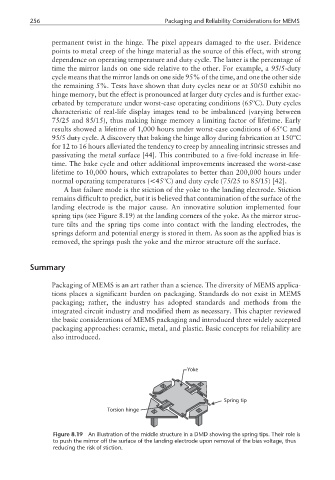
A last failure mode is the stiction of the yoke to the landing electrode. Stiction
remains difficult to predict, but it is believed that contamination of the surface of the
landing electrode is the major cause. An innovative solution implemented four
spring tips (see Figure 8.19) at the landing corners of the yoke. As the mirror struc-
ture tilts and the spring tips come into contact with the landing electrodes, the
springs deform and potential energy is stored in them. As soon as the applied bias is
removed, the springs push the yoke and the mirror structure off the surface.
Summary
Packaging of MEMS is an art rather than a science. The diversity of MEMS applica-
tions places a significant burden on packaging. Standards do not exist in MEMS
packaging; rather, the industry has adopted standards and methods from the
integrated circuit industry and modified them as necessary. This chapter reviewed
the basic considerations of MEMS packaging and introduced three widely accepted
packaging approaches: ceramic, metal, and plastic. Basic concepts for reliability are
also introduced.
Yoke
Spring tip
Torsion hinge
Figure 8.19 An illustration of the middle structure in a DMD showing the spring tips. Their role is
to push the mirror off the surface of the landing electrode upon removal of the bias voltage, thus
reducing the risk of stiction.