
Page 122 - Analog and Digital Filter Design
P. 122
119
Poles and Zeroes
Pole
Stopband Filter Attenuation Pole Real Imaginary
Frequency Order (dB) Zero Part Part
1.1 9 58 2.302010 0.341 7308 0.5448127
1.392020 0.1731486 0.8472668
1.170604 0.0695 I29 0,9697934
1.106502 0.0178438 1.0105670
0.4482750
1.2 7 50 2.228609 0.371 1950 0.627191 I
1.393320 0.1614481 0.928552 1
1.2 I6500 0.0410804 1.0244980
0.5197208
1.3 7 59 2.533631 0.3667336 0.5862 I46
1.540439 0.1790991 0.91001 19
1.320986 0.0493328 1.0282 150
0.48 18349
1.4 52 4.6 18428 0.5006298 0.3655174
1.825298 0.2688599 0.8608322
1.434274 0.0742502 1.0425360
1.5 57 2.33 1876 0.4170394 0.7757674
1.557406 0.1 I41299 1.066 1520
0.6497566
2.0 5 58 3.250805 0.42909 17 0.72 13293
2.089247 0. I389126 1.0735670
0.5909335
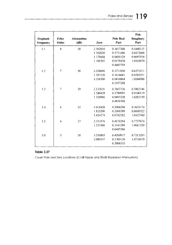
Table 3.27
Cauer Pole and Zero Locations (0.ldB Ripple and 50dB Stopband Attenuation)