
Page 120 - Analog and Digital Filter Design
P. 120
Polesand Zeroes 1 1 7
Cauer Pole and Zero Locations
Tables of pole and zero locations for some Cauer or elliptic function filters have
been produced by Zverev,' but more extensive tables are given by Huelsman,'
and by Stephenson.4 These tables require the passband ripple, stopband atten-
uation, and the passband to stopband frequency ratio. For Cauer filters, the
passband edge has the same attenuation as the ripple value; the response is not
normalized to the 3dB attenuation point. The reason is simply that the 3dB
point is difficult to calculate.
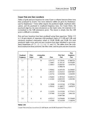
Pole and zero locations have been produced using these equations. Tables 3.25
to 3.30 give details of responses with passband ripple of 0.1 dB and I dB, and
minimum stopband attenuation values of 30dB, 40dB, and 50dB. For each
passband ripple value, pole and zero locations have been tabulated to give stop-
band frequencies of 1.1, 1.2, 1.3, 1.4, 1.5, and 2.0. The tables show the stop-
band attenuation (loss) achieved, the filter order, and the pole and zero locations.
Pole
Stopband Filter Attenuation Pole Real Imaginary
Frequency Order (dB) Zero Part Part
1.1 7 39 1.874772 0.3726 10 1 0.7068724
1.23448 1 0.1291 187 0.9574289
1.1 109 13 0.0282793 1.0182750
0.5996378
1.2 39 3.598982 0.5476350 0.4296885
1.495323 0.23543 15 0.9076983
1.222716 0.0545950 1.0342950
I .3 34 1.936892 0.3997024 0.8289210
1.342284 0.092 5 5 59 1.0585590
0.7 I55 148
1.4 5 39 2.138080 0.4105364 0.7979046
1.450 162 0.1048577 1.0630270
0.6759573
I .5 5 43 2.331876 0.4170394 0.7757674
1.557406 0.1 141299 1.066 1 520
0.6497566
2.0 4 41 4.9221 13 0.6704486 0.5356409
2.143189 0.21 62558 1.1 168230
Table 3.25
Cauer Pole and Zero Locations (O.ldB Ripple and 30dB Stopband Attenuation)