
Page 123 - Analog and Digital Filter Design
P. 123
Pole
Stopband Filter Attenuation Pole Real Imaginary
Frequency Order (dB) Zero Part Part
~
1.1 5 30 1.480909 0.2021778 0.8048071
1.122194 0.0346257 1.0002280
0.4466498
1.2 5 38 1.722895 0.2175734 0.7481695
1.233340 0.0480848 0.9984797
0.3915898
1.3 4 32 2.845330 0.3773649 0.5212809
1.368223 0.0887571 0.9976692
1.4 4 36 3.169408 0.3702850 0.4971396
1.480785 0.0977832 0.9955948
1.5 4 39 3.478406 0.3649968 0.4806942
1.592342 0.1044116 0.9939388
2.0 3 34 2.270068 0.2170489 0.9815897
0.5400008
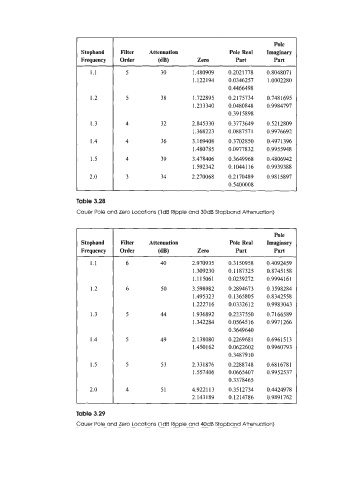
Table 3.28
Cauer Pole and Zero Locations (1dB Ripple and 3OdB Stopband Attenuation)
Pole
Stopband Filter Attenuation Pole Real Imaginary
Frequency Order (W Zero Part Part
1.1 6 40 2.970935 0.3150958 0.4092459
1.309230 0.1 187325 0.8745158
1.1 15061 0.0239272 0.99941 6 1
1.2 6 50 3.598982 0.2894673 0.3598284
1.495323 0.1365805 0.8342558
1.222716 0.0332612 0.9983043
1.3 5 44 1.936892 0.2237550 0.7 166589
1.342284 0.0564516 0.9971266
0.3649640
1.4 5 49 2.138080 0.2269681 0.6961513
1.450 162 0.0622602 0.9960793
0.3487910
1.5 5 53 2.33 1876 0.2288748 0.6816781
1.557406 0.0665407 0.9952537
0.3378465
2.0 4 51 4.922113 0.3512734 0.4424978
2.143 189 0.1214786 0.9891762
Table 3.29
Cauer Pole and Zero Locations (Id6 Ripple and 40dB Stopband Attenuation)