
Page 128 - Analog and Digital Filter Design
P. 128
4
CHAPTER
ANALOG LOWPASS FILTERS
This chapter describes how to design active or passive lo~vpass filters to almost
any desired specification. Formulae and examples of how to use them are given
for the denormalization of component values previously given in Chapters 2
and 3.
Passive Filters
Passive filters are the simplest to design from the normalized model. The model
itself is a lowpass design, although normalized for a passband that extends from
DC to 1 rad/s and is terminated with a 1 R load resistance. Denormalization
for a higher load impedance requires component values to be scaled to have a
higher impedance. The impedance of an inductor is proportional to its induc-
tance, but the impedance of a capacitor is inversely proportional to its capac-
itance. Thus, if the load resistance is a more practical 50R. inductance values
are increased fifty-fold and capacitance values are reduced fifty-fold (to increase
their impedance).
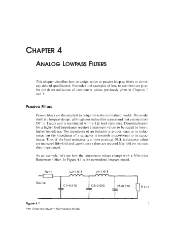
As an example, let's see how the component values change with a fifth-order
Butterworth filter. In Figure 4.1 is the normalized lowpass model.
-- -- -- R L=l
Source
--
--
C1=0.618
-- C3=2.000
C5=0.618