
Page 130 - Analog and Digital Filter Design
P. 130
127
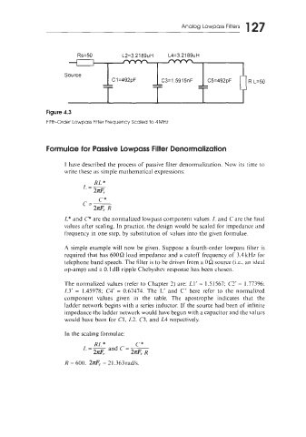
Analog Lowpass Filters
Source
-- -- -- R L=50
--
--
--
C 1 =492pF
C3=1.5915nF
C5=492pF
Formulae for Passive Lowpass Filter Denormalization
I have described the process of passive filter denormalization. Now its time to
write these as simple mathematical expressions:
C*
C=--
2z& R
L* and C* are the normalized lowpass component values. L and Care the tinal
values after scaling. In practice, the design would be scaled for impedance and
frequency in one step, by substitution of values into the given formulae.
A simple example will now be given. Suppose a fourth-order lowpass filter is
required that has 600R load impedance and a cutoff frequency of 3.4kHz for
telephone band speech. The filter is to be driven from a OR source (Le.. an ideal
op-amp) and a 0.1 dB ripple Chebyshev response has been chosen.
The normalized values (refer to Chapter 2) are: L.1’ = 1.51567; C2‘ = 1.77396:
L3’ = 1.45978; C4‘ = 0.67474. The L’ and C’ here refer to the normalized
component values given in the table. The apostrophe indicates that the
ladder network begins with a series inductor. If the source had been of infinite
impedance the ladder network would have begun with a capacitor and the values
would have been for C1, L2. C3, and L4 respectively.
In the scaling formulae:
RL * C*
L=- and C=-
2z& 2Z& R
R = 600. 2z& = 2 1.363 radls.