
Page 134 - Analog and Digital Filter Design
P. 134
131
Analog Lowpass Filters
Live =;
Neutral =20: =; Y
Y xo:
Y
==
-- -- -- --
Y
Earth
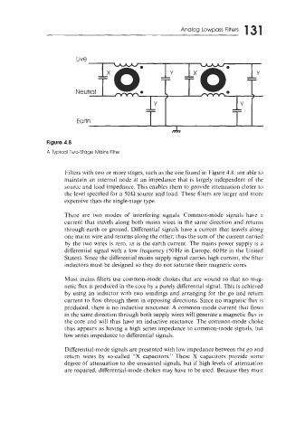
Figure 4.8
A Typical Two-Stage Mains Filter
Filters with two or more stages, such as the one found in Figure 4.8, are able to
maintain an internal node at an impedance that is largely independent of the
source and load impedance. This enables them to provide attenuation closer to
the level specified for a 50R source and load. These filters are larger and more
expensive than the single-stage type.
There are two modes of interfering signals. Common-mode signals hai.e a
current that travels along both mains wires in the same direction and returns
through earth or ground. Differential signals have a current that travels along
one mains wire and returns along the other; thus the sum of the current carried
by the two wires is zero, as is the earth current. The mains power supply is a
differential signal with a low frequency (50Hz in Europe, 60Hz in the United
States). Since the differential mains supply signal carries high current, the filter
inductors must be designed so they do not saturate their magnetic cores.
Most mains filters use common-mode chokes that are wound so that no mag-
netic flux is produced in the core by a purely differential signal. This is achieved
by using an inductor with two windings and arranging for the go and return
current to flow through them in opposing directions. Since no magnetic flux is
produced, there is no inductive reactance. A common-mode current that flo~vs
in the same direction through both supply wires will generate a magnetic flux in
the core and will thus have an inductive reactance. The common-mode choke
thus appears as having a high series impedance to common-mode signals, but
low series impedance to differential signals.
Differential-mode signals are presented with low impedance between the go and
return wires by so-called "X capacitors." These X capacitors provide some
degree of attenuation to the unwanted signals, but if high levels of attenuation
are required, differential-mode chokes may have to be used. Because they must