
Page 137 - Analog and Digital Filter Design
P. 137
1 34 Analog and Digital Filter Design
By letting R1 and R2 equal 1 R in the normalized design, the values of C1 and
C2 can easily be calculated.
In the case of Butterworth filters, o,,= 1 and C2 = 0, that is, the reciprocal
of c1.
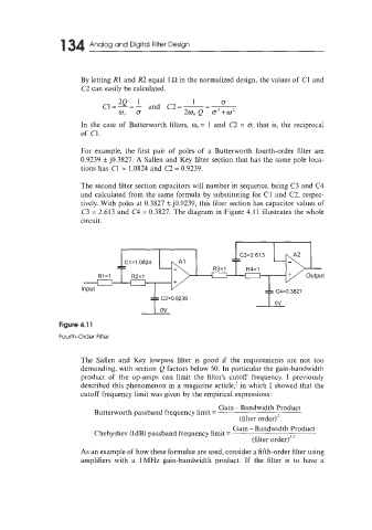
For example, the first pair of poles of a Butterworth fourth-order filter are
0.9239 f j0.3827. A Sallen and Key filter section that has the same pole loca-
tions has C1 = 1.0824 and C2 = 0.9239.
The second filter section capacitors will number in sequence, being C3 and C4
and calculated from the same formula by substituting for C1 and C2. respec-
tively. With poles at 0.3827 ? j0.9239, this filter section has capacitor values of
C3 = 2.613 and C4 = 0.3827. The diagram in Figure 4.11 illustrates the whole
circuit.
C3=2.613
C 1 =1.0824
R3=1 R4=1
RI=l R2=1
Input
f gcv2=0.9239 T c4=0'3827
Figure 4.1 1
Fourth-Order Filter
The Sallen ant Key lowpass filter is good if tL.e requirements are not too
demanding, with section Q factors below 50. In particular the gain-bandwidth
product of the op-amps can limit the filter's cutoff frequency. I previously
described this phenomenon in a magazine article,' in which I showed that the
cutoff frequency limit was given by the empirical expressions:
Gain - Bandwidth Product
Butterworth passband frequency limit =
(filter order)'
Gain - Bandwidth Product
Chebyshev (1dB) passband frequency limit =
(filter order)3.'
As an example of how these formulae are used, consider a fifth-order filter using
amplifiers with a lMHz gain-bandwidth product. If the filter is to have a