
Page 133 - Analog and Digital Filter Design
P. 133
1 30 Analog and Digital Filter Design
able leakage current should be specified. The electrical specification must comply
with national safety standards.
Filters work on the principal of providing a large discontinuity in the charac-
teristic impedance seen by an unwanted signal. The intention is to reflect most
of this unwanted energy back to its source. In the case of mains supplies, the
source and load impedance varies wildly with frequency. The source impedance
is variable over time and can be anywhere from 2R to 200052. The actual imped-
ance is dependent on the loads that are connected to it and the frequency of
interest. The characteristic impedance of the mains lead to the load is around
150R, and the load itself may have a variable impedance.
Mains filters are tested with a 50R source and load impedance because most
RF test equipment has a characteristic impedance of 50R. This allows consis-
tent test results and allows direct comparison between one design and another.
However, because the source and load impedance is not generally 50R in
practical situations, the attenuation predicted for a design based on this
specification is generally optimistic compared with its performance in working
equipment.
Inductors resonate at some frequencies due to unwanted interwinding capaci-
tance. Similarly, capacitors resonate at some frequencies due to unwanted lead
inductance. In a filter the performance of the inductors and capacitors used
can depend critically on the resonant frequencies and on the source and load
impedance.
Neutral ==xo:
Y
=;
--
--
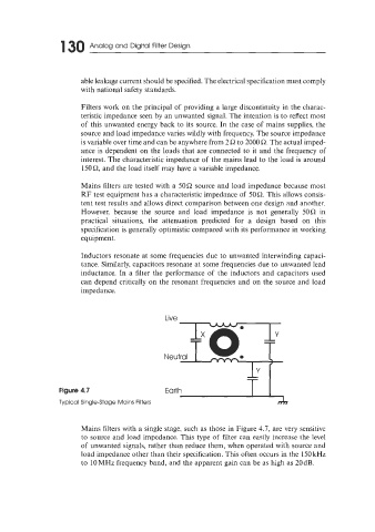
Figure 4.7 Earth Y
Typical Single-Stage Mains Filters A
Mains filters with a single stage, such as those in Figure 4.7, are very sensitive
to source and load impedance. This type of filter can easily increase the level
of unwanted signals, rather than reduce them, when operated with source and
load impedance other than their specification. This often occurs in the 15OkHz
to 10MHz frequency band, and the apparent gain can be as high as 20dB.