
Page 131 - Analog and Digital Filter Design
P. 131
1 28 Analog and Digital Filter Design
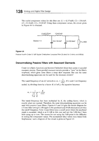
The scaled component values for this filter are: L1 = 42.57mH; C2 = 138.4nF;
L3 = 41.0mH; C4 = 52.64nF. Using these component values, the circuit given
in Figure 4.4 is obtained.
L1=42.57mH L3=41mH
Source = 0
Figure 4.4
Passive Fourth-Order 0.1 dB Ripple Chebyshev Lowpass Filter (Scaled for 3.4kHz and 600n)
Denormalizing Passive Filters with Resonant Elements
Cauer (or elliptic function) and Inverse Chebyshev filters have series or parallel
resonant circuits. These parallel resonant circuits provide a "zero" in the filter's
stopband, which gives these filters a steep skirt response. But can the same
denormalizing equations can be used for the resonant circuits?
1
The tuned frequency of an LC network is: a,, -
If L and C are frequency
=
m-
scaled, by dividing them by a factor K (=2 nFc), the equation becomes:
The tuned frequency has been multiplied by K, the scaling factor, which is
exactly what was wanted. Therefore, the same denormalizing equations can be
used with passive Cauer filters. Figures 4.5 and 4.6 give the circuit diagram for
a Cauer filter having 0.1 dB ripple in the passband and 59 dB attenuation at twice
the cutoff frequency. Note: Cauer filters have a cutoff point where the passband
ripple is exceeded, which is at 0.1 dB in this case and not the 3 dB that I have
been using up to now. The reason for not using the 3dB point is the difficulty
in scaling the component values. The normalized filter values were taken from
Stephenson,' and a diagram of the circuit is given in Figure 4.5.