
Page 136 - Analog and Digital Filter Design
P. 136
133
Analog Lowpass Filters
-
Output
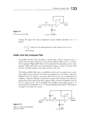
Figure 4.9
First-Order Active Filter I ov
Letting R1 equal 1R in LA normalized lo~vpass model. calculation of ('I is
simple:
I
C1 = - , where o is the pole position on the negative real axis of
CT
the S-plane
Sallen and Key Lowpass Filter
The Sallen and Key filter provides a second-order all-pole response and i\ ;I
simple active lowpass design. It can be used for Bessel. Butterworth. or Chebk-
shev responses. High-order filters can be produced by cascading second-order
sections. Odd-order filters can be produced by using a series of second-order
sections and then adding a first-order section at the end.
The Sallen and Key filter uses an amplifier (which may be connected as it unit!
gain buffer) with a network of resistors and capacitors at the input. Capacitive
feedback from the output is also used. and this can give rise to peaking in the
frequency response. Peaking is required in second-order circuits where the Q is
greater than unity and occurs due to phase shifts around the feedback loop. If
the Q is large, say Q = 10, for example. the amplifier is providing a gain of IO
that restricts its bandwidth to 0.1 of the gain-bandwidth product. The diagram
in Figure 4.10 shows the circuit.
Figure 4.10
Sallen and Key Lowpass Filter
(Second-Order)