
Page 132 - Analog and Digital Filter Design
P. 132
Analog Lowpass Filters 1 29
II II
II
II
-- C2=0.07317 -- C4=0.20038 --
lnput -- -- -- R2=1
C1=1.08758 C3=1.79387 C5=0.97720
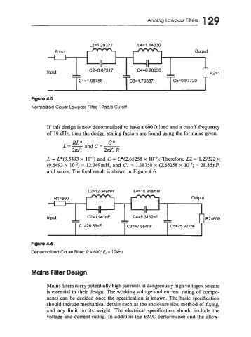
Figure 4.5
Normalized Cauer Lowpass Filter. 1 Rad/s Cutoff
If this design is now denormalized to have a 600a load and a cutoff frequency
of lOkHz, then the design scaling factors are found using the formulae given.
L = L*(9.5493 x and C = C(2.65258 x 10⁻⁸). Therefore, L2 = 1.29322 x
(9.5493 x = 12.349mH, and C1 = 1.08758 x (2.65258 x lo-') = 28.85nF,
and so on. The final result is shown in Figure 4.6.
II II
II
--
--
lnput -- C2=1.94inF -- C4=5.3152nF -- -- R2=600
C1=28.85nF C3=47.584nF C5=25.921 nF
Flgure 4.6
Denormalized Cauer Filter: R = 600; F, = 10 kHz
Mains Filter Design
Mains filters carry potentially high currents at dangerousl! high volt ges, so care
is essential in their design. The working voltage and current rating of compo-
nents can be decided once the specification is known. The basic specification
should include mechanical details such as the enclosure size, method of king,
and any limit on its weight. The electrical specification should include the
voltage and current rating. In addition the EMC performance and the allow-