
Page 129 - Analog and Digital Filter Design
P. 129
1 26 Analog and Digital Filter Design
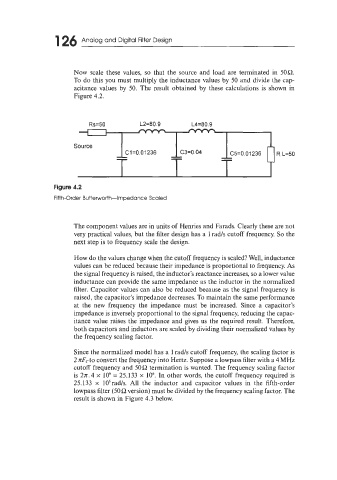
Now scale these values, so that the source and load are terminated in 50R.
To do this you must multiply the inductance values by 50 and divide the cap-
acitance values by 50. The result obtained by these calculations is shown in
Figure 4.2.
Rs=50 L2=80.9 L4=80.9
i 1
Source
- C3=0.04 C5=0.01236 R L=50
C1=0.01236
Figure 4.2
Fifth-Order Butterworth-Impedance Scaled
The component values are in units of Henries and Farads. Clearly these are not
very practical values, but the filter design has a 1 rad/s cutoff frequency. So the
next step is to frequency scale the design.
How do the values change when the cutoff frequency is scaled? Well, inductance
values can be reduced because their impedance is proportional to frequency. As
the signal frequency is raised, the inductor’s reactance increases, so a lower value
inductance can provide the same impedance as the inductor in the normalized
filter. Capacitor values can also be reduced because as the signal frequency is
raised, the capacitor’s impedance decreases. To maintain the same performance
at the new frequency the impedance must be increased. Since a capacitor’s
impedance is inversely proportional to the signal frequency, reducing the capac-
itance value raises the impedance and gives us the required result. Therefore,
both capacitors and inductors are scaled by dividing their normalized values by
the frequency scaling factor.
Since the normalized model has a 1 rad/s cutoff frequency, the scaling factor is
2 nFcto convert the frequency into Hertz. Suppose a lowpass filter with a 4 MHz
cutoff frequency and 50 R termination is wanted. The frequency scaling factor
is 2n.4 x lo6 = 25.133 x IO6. In other words, the cutoff frequency required is
25.133 x 1O6rad/s. All the inductor and capacitor values in the fifth-order
lowpass filter (50R version) must be divided by the frequency scaling factor. The
result is shown in Figure 4.3 below.