
Page 121 - Analog and Digital Filter Design
P. 121
1 1 8 Analog and Digital Filter Design
Pole
Stopband Filter Attenuation Pole Real Imaginary
Frequency Order (a) Zero Part Part
1.1 8 49 3.886673 0.4667635 0.3448176
1.542858 0.2464161 0.7959576
1.194614 0.0923402 0.9640234
1.108280 0.0222051 1.0136280
1.2 7 50 2.228609 0.3711950 0.627191 1
1.393320 0.161448 1 0.9285521
1.2 16500 0.0410804 1.0244980
0.5 197208
1.3 6 46 4.130255 0.5189843 0.3893 137
1.664290 0.2561887 0.8800071
1.328862 0.0660706 1.0392380
1.4 6 52 4.618428 0.5006298 0.3655174
1.825298 0.2688599 0.8608322
1.434274 0.0742502 1.0425360
1.5 5 43 2.33 1876 0.4170394 0.7757674
1.557406 0.1141299 1.0661520
0.6497566
2.0 4 41 4.9221 13 0.6704486 0.5356409
2.143 189 0.2162558 1.1 168230
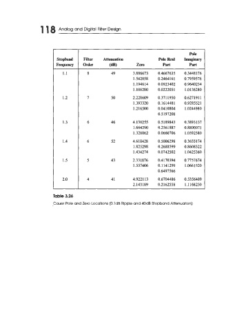
Table 3.26
Cauer Pole and Zero Locations (0.1 dB Ripple and 40dB Stopband Attenuation)